Learn Basics Engineering Graphics EG Tutorial As Per GTU Syllabus
What is Engineering Graphics ?
An engineering drawing, a type of technical drawing, is used to fully and clearly define requirements for engineered items. Engineering drawing (the activity) produces engineering drawings (the documents).
Syllabus of Engineering Graphics ?
Topic 01 : Introduction to Engineering Graphics:
Drawing instruments and accessories, BIS – SP 46. Use of plane scales, Diagonal Scales and Representative Fraction
Topic 02 : Engineering Curves:
Classification and application of Engineering Curves, Construction of Conics, Cycloidal Curves, Involutes and Spirals along with normal and tangent to each curve
Topic 03 : Projections of Points and Lines:
Introduction to principal planes of projections, Projections of the points located in same quadrant and different quadrants, Projections of line with its inclination to one reference plane and with two reference planes. True length and inclination with the reference planes
Topic 04 : Projections of Planes:
Projections of planes (polygons, circle and ellipse) with its inclination to one reference plane and with two reference planes, Concept of auxiliary plane method for projections of the plane
Topic 05 : Projections of Solids and Section of Solids:
Classification of solids. Projections of solids (Cylinder, Cone, Pyramid and Prism) along with frustum with its inclination to one reference plane and with two reference planes. Section of such solids and the true shape of the section
Topic 06 : Orthographic Projections:
Fundamental of projection along with classification, Projections from the pictorial view of the object on the principal planes for view from front, top and sides using first angle projection method and third angle projection method, full sectional view
Topic 07 : Isometric Projections and Isometric View or Drawing:
Isometric Scale, Conversion of orthographic views into isometric projection, isometric view or drawingBenefits of Engineering Graphics ?
- To develop the ability to produce simple engineering drawing and sketches based on current practice.
- To develop the skills to read manufacturing and construction drawings used in industry.
- To develop a working knowledge of the layout of plant and equipment.
- To develop skills in abstracting information from calculation sheets and schematic diagrams to produce working drawings for manufacturers, installers and fabricators.
- Technical drawing is the preferred method of drafting in all engineering fields, including, but not limited to, civil engineering, electrical engineering, mechanical engineering and architecture.
Where Engineering Graphics used?
- Standardization and disambiguation
Engineering drawings specify requirements of a component or assembly which can be complicated. Standards provide rules for their specification and interpretation. In 2011, a new revision of ISO 8015 was published containing the Invocation Principle. This states that, "Once a portion of the ISO geometric product specification (GPS) system is invoked in a mechanical engineering product documentation, the entire ISO GPS system is invoked." It also goes on to state that marking a drawing "Tolerancing ISO 8015" is optional. The implication of this is that any drawing using ISO symbols can only be interpreted to ISO GPS rules. The only way not to invoke the ISO GPS system is to invoke a national or other standard. Now in 2015 there is a new standardisation called BS 8888, this is now used for all standard and technical drawings.
Since there are only two widely standardized definitions of size, there is only one real alternative to ISO GPS, i.e. ASME Y14.5 and Y14.5M (most recently revised in 2009). Standardization also aids internationalization, because people from different countries who speak different languages can read the same engineering drawing, and interpret it the same way. To that end, drawings should be as free of notes and abbreviations as possible so that the meaning is conveyed graphically.
Important note! The 'manufacturing' of a technical drawing however is as difficult as the actual production of the design it describes. Therefore engineers must think very clearly about what is placed on a drawing, i.e Dimensioning and tolerancing principles. (GD&T). Ideally each party knows exactly how to read and interpret such principles, but practise shows it is not as easy.
- Media
For centuries, until the post-World War II era, all engineering drawing was done manually by using pencil and pen on paper or other substrate (e.g., vellum, mylar). Since the advent of computer-aided design (CAD), engineering drawing has been done more and more in the electronic medium with each passing decade. Today most engineering drawing is done with CAD, but pencil and paper have not disappeared.
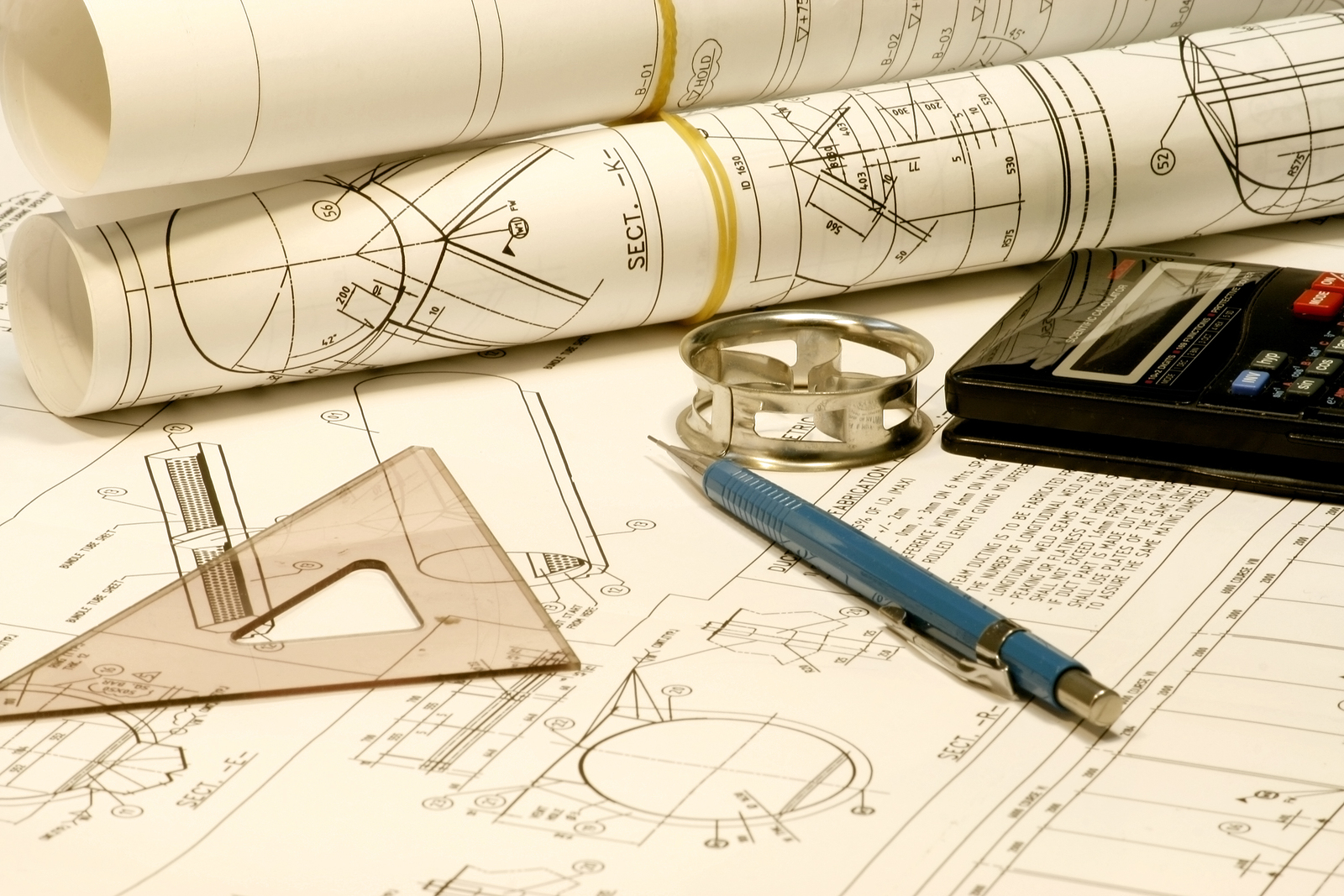
Some of the tools of manual drafting include pencils, pens and their ink, straightedges, T-squares, French curves, triangles, rulers, protractors, dividers, compasses, scales, erasers, and tacks or push pins. (Slide rules used to number among the supplies, too, but nowadays even manual drafting, when it occurs, benefits from a pocket calculator or its onscreen equivalent.) And of course the tools also include drawing boards (drafting boards) or tables. The English idiom "to go back to the drawing board", which is a figurative phrase meaning to rethink something altogether, was inspired by the literal act of discovering design errors during production and returning to a drawing board to revise the engineering drawing. Drafting machines are devices that aid manual drafting by combining drawing boards, straightedges, pantographs, and other tools into one integrated drawing environment. CAD provides their virtual equivalents.
Producing drawings usually involves creating an original that is then reproduced, generating multiple copies to be distributed to the shop floor, vendors, company archives, and so on. The classic reproduction methods involved blue and white appearances (whether white-on-blue or blue-on-white), which is why engineering drawings were long called, and even today are still often called, "blueprints" or "bluelines", even though those terms are anachronistic from a literal perspective, since most copies of engineering drawings today are made by more modern methods (often inkjet or laser printing) that yield black or multicolour lines on white paper. The more generic term "print" is now in common usage in the U.S. to mean any paper copy of an engineering drawing. In the case of CAD drawings, the original is the CAD file, and the printouts of that file are the "prints".
- Relationship to model-based definition (MBD/DPD)
For centuries, engineering drawing was the sole method of transferring information from design into manufacture. In recent decades another method has arisen, called model-based definition (MBD) or digital product definition (DPD). In MBD, the information captured by the CAD software app is fed automatically into a CAM app (computer-aided manufacturing), and is translated via postprocessor into other languages such as G-code, which is executed by a CNC machine tool (computer numerical control). Thus today it is often the case that the information travels from the mind of the designer into the manufactured component without having ever been codified by an engineering drawing. In MBD, the dataset, not a drawing, is the legal instrument. The term "technical data package" (TDP) is now used to refer to the complete package of information (in one medium or another) that communicates information from design to production (such as 3D-model datasets, engineering drawings, engineering change orders (ECOs), spec revisions and addenda, and so on). However, even in the MBD era, where theoretically production could happen without any drawings or humans at all, it is still the case that drawings and humans are involved. It still takes CAD/CAM programmers, CNC setup workers, and CNC operators to do manufacturing, as well as other people such as quality assurance staff (inspectors) and logistics staff (for materials handling, shipping-and-receiving, and front office functions). These workers often use drawings in the course of their work that have been produced by rendering and plotting (printing) from the MBD dataset. When proper procedures are being followed, a clear chain of precedence is always documented, such that when a person looks at a drawing, s/he is told by a note thereon that this drawing is not the governing instrument (because the MBD dataset is). In these cases, the drawing is still a useful document, although legally it is classified as "for reference only", meaning that if any controversies or discrepancies arise, it is the MBD dataset, not the drawing, that governs.